How full-field infrared monitoring catches the heat-treat defects that thermocouples never see before they become scrap, rework, or a recall.
Hot stamping is one of the most thermally demanding manufacturing processes in the automotive supply chain. A boron steel blank must be heated to austenitizing temperatures between 900°C and 950°C, transferred rapidly into a forming die, shaped, and quenched all within a window of seconds.
The result, when executed perfectly, is an ultra-high-strength martensitic part with tensile strengths exceeding 1,500 MPa that would be impossible to form at room temperature.1
But “executed perfectly” is the operative phrase. The margin for thermal error in hot stamping is razor-thin. A cold zone of just 50–80°C in one region of a blank can mean incomplete austenitization, a mixed microstructure, and a part that fails crash safety specifications, even if it looks fine on the press line.
A die with blocked water channels will cool unevenly, producing residual stresses that manifest as dimensional distortion or springback weeks into a production run.
At Emitted Energy, we have deployed full-field infrared thermal monitoring systems across hot stamping operations for global OEMs and Tier 1 suppliers. What we consistently find is the same: traditional point-sensor monitoring leaves entire categories of failure modes completely invisible.
This article lays out precisely why, what those failure modes are, and how real-time thermal imaging closes the gap.
P R O C E S S F U N D A M E N T A L S
The Critical Thermal Windows in Hot Stamping
| STAGE 01 | STAGE 02 | STAGE 03 | STAGE 04 |
| Furnace Soak | Transfer | Forming | Quench in Die |
| 900–950°C | < 3–5 sec | ≥ 650°C | > 27°C/sec |
Every one of these stages has a thermal specification. The blank must reach full austenite transformation in the furnace. It must arrive at the die above the martensite start temperature. The die must cool at a rate sufficient to suppress ferrite and bainite formation. Any deviation in any zone of the part produces a compromised microstructure.2
The challenge is that a B-pillar or door ring is not a uniform geometry. Thickness varies. Flanges, radii, and holes all interact with heat differently. A single thermocouple or spot pyrometer tells you the temperature at one point. It tells you nothing about the heat distribution across the entire blank, and distribution is everything.
C R I T I C A L D E F E C T M E C H A N I S M
How Thermal Variation Corrupts Part Geometry in Hot Stamping
One of the most underappreciated consequences of uneven heat treatment in hot stamping is its direct impact on final part geometry. This is not a secondary effect; it is a primary failure mechanism with multiple pathways.
Differential Thermal Expansion and Springback
When regions of a blank are at significantly different temperatures as the die closes, the material’s flow stress varies dramatically across the part surface. Hotter zones are more compliant; cooler zones resist deformation. This mismatch creates residual stress gradients that survive quenching and manifest as springback, twist, or warpage after the part is ejected.
A blank with a cold zone at 650°C, forming alongside regions at 820°C, can produce dimensional deviations of several millimeters in flanged features, well outside the ±0.5 mm tolerance typical for structural BIW components.3
Partial Phase Transformation and Strength Gradients
Martensitic transformation requires both sufficient austenitization in the furnace and sufficient quench rate in the die. If a region of the blank enters the die below the martensite start temperature, the quench may produce a mixed microstructure of martensite, bainite, and retained austenite. This zone will have lower hardness, lower tensile strength, and different elastic properties than the surrounding fully martensitic material. The part may pass visual inspection and even basic hardness spot checks, yet fail energy absorption requirements in crash simulation—because the failure mode is distributed, not localized.
Die Contact and Cooling Asymmetry in Hot Stamping
Material buildup on die surfaces (lubricant residue, oxide scale, or scale transferred from blanks) creates an insulating layer that reduces heat transfer rates during quench. Even a thin, uniform layer can drop local cooling rates below the critical martensite threshold.
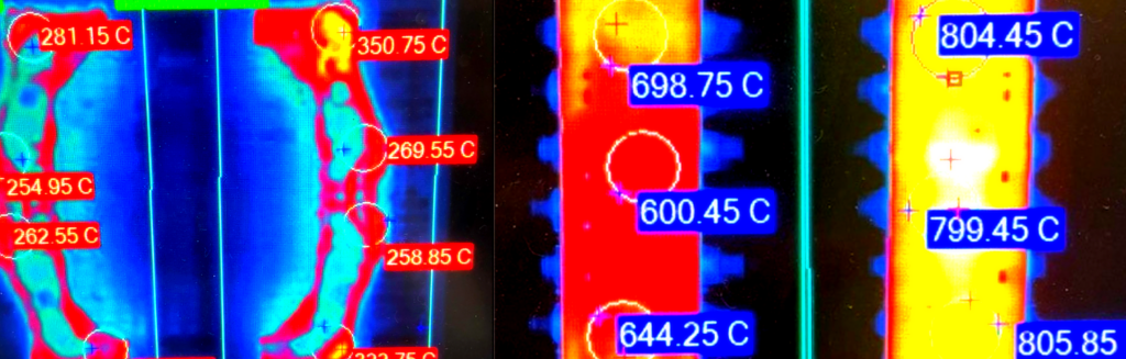
What thermal imaging reveals in practice is a characteristic “hot spot” pattern post-stamp: the region above the buildup cools more slowly, retains higher temperature longer, and appears as a persistent heat signature in post-stamp images. Left undetected, this defect propagates across an entire production run before a metallurgical failure triggers a containment event.
Hot Stamping Application Field Observation: In a documented case study at a high-throughput OEM facility, Emitted Energy’s Enlighten+ system identified a persistent 350°C hot spot on a post-stamp part in a region that had no thermocouple coverage. Inspection confirmed die buildup, causing poor contact. Maintenance performed; defect eliminated.
Without thermal imaging in this hot stamping process, this pattern would have gone undetected across hundreds of parts per shift.
R O O T C A U S E A N A L Y S I S
Mapping Defect Signatures to Their Thermal Origins in Hot Stamping
One of thermal imaging’s most powerful contributions to hot stamping is its ability to support
systematic root cause analysis. Because it captures the full spatial temperature distribution at each stage of the process, it creates a visual fingerprint that can be compared across cycles, shifts, and production runs.
| METRIC 01 | METRIC 02 | METRIC 03 | METRIC 04 |
| PART SURFACE COVERAGE | FULL-FIELD SCAN TIME | MEASUREMENT ACCURACY | TRACEABLE THERMAL RECORD PER PART |
| 100% | <1s | ±2°C | 100% |
The Hot Stamping Defect Matrix: Thermal Fingerprints vs. Root Causes
The table below maps the most common hot stamping defect types to their thermal signatures and the process variable responsible:
| DEFECT | THERMAL SIGNATURE | ROOT CAUSE | DETECTABILITY |
| Incomplete martensite transformation | Pre-stamp cold zone <720°C | Oven zone degradation / insufficient soak | THERMAL IMAGING |
| Dimensional distortion / springback | Gradient >80°C across blank at die close | Uneven oven heating or transfer delay | THERMAL IMAGING |
| Die buildup / poor quench contact | Post-stamp hot zone >280°C | Lubricant/scale accumulation on the die | THERMAL IMAGING |
| Water channel blockage | Asymmetric post-stamp heat pattern | Fouled cooling circuit | THERMAL IMAGING |
| Microcracking from overheating | Pre-stamp zone >980°C | Oven over-temperature / dwell excess | PYROMETER MISSES EXTENT |
The pattern is consistent: each defect has a distinctive thermal fingerprint that appears at a specific stage of the process. Without full-field imaging, that fingerprint never gets recorded. Engineers are left working backward from downstream failures, metallurgical rejects, CMM deviations, and crash-test anomalies with no direct evidence of the thermal event that caused them.
P R O C E S S C O N T R O L
Correlating Thermal Data to Defect Rates and Acting on It
Knowing that thermal variation exists in hot stamping is necessary but not sufficient. The competitive advantage comes from closing the control loop: detecting a thermal anomaly, correlating it to a known failure mode, and triggering a corrective response before a defective part leaves the press.
Automated Alarming Against Defined Thresholds
Emitted Energy’s Enlighten+ software allows engineers to define region-of-interest (ROI) zones on the thermal image that correspond to metallurgically critical areas of the part. Each ROI carries a min/max temperature threshold based on the validated process recipe. If any ROI falls outside the specification on the pre-stamp image, the system flags the cycle before the blank is formed. This is the equivalent of 100% in-process inspection of the thermal condition of every part, every cycle, with zero manual operator involvement.
Trend Analysis for Predictive Maintenance
Because Enlighten+ timestamps and archives every thermal image and alarm event, process engineers can plot temperature trends across weeks of production. An oven zone that is gradually drifting cooler by 5°C per week will be invisible to a thermocouple alarm set at a fixed threshold until it crosses that threshold, triggering a potential metallurgical nonconformance. Thermal imaging reveals drift while parts are still within spec, enabling proactive rather than reactive maintenance scheduling.
Recipe Validation and Die Qualification
Thermal imaging is also the gold standard for validating new process recipes and qualifying new tooling. When a new die is introduced, or a recipe is changed, the first production cycles can be fully characterized thermally, die temperature uniformity confirmed, quench rate distribution mapped, and pre-stamp uniformity validated. This data becomes part of the PPAP and APQP record, providing documented evidence that the process was thermally validated, not just dimensionally checked.
CQI-9 Compliance and Continuous Pyrometry Verification in Hot Stamping
For automotive suppliers, thermal validation is more than best practice: it is a compliance mandate. The AIAG’s CQI-9 (Special Process: Heat Treat System Assessment) standard requires rigorous, documented control of all thermal processing variables to ensure microstructural integrity.
Historically, meeting CQI-9 requirements meant relying heavily on periodic Saturation Accuracy Tests (SAT) and Temperature Uniformity Surveys (TUS) of the furnace layers. However, once the blank leaves the furnace, traditional pyrometry leaves a compliance blind spot during the critical transfer and die-quench phases.
By integrating Emitted Energy’s thermal imaging solutions, manufacturers elevate their CQI-9 compliance from a periodic checklist to continuous, real-time verification. The ADVISOR+ Thermal Monitoring Process System™ generates an unalterable, 100% traceable thermal record for every single part processed.
The detailed spatial data provided by our closed-loop system directly supports CQI-9 requirements for continuous process monitoring and equipment qualification. Confidence in every process means that auditors have definitive, undeniable proof that every square millimeter of the component underwent the precise thermal cycle required to achieve full martensitic transformation.
T H E E M I T T E D E N E R G Y S O L U T I O N
ADVISOR+ and Enlighten+ with FLIR A-Series: Full-Field Thermal Intelligence in Hot Stamping
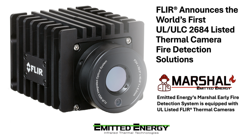
The Emitted Energy ADVISOR+™ Thermal Process Monitoring System is purpose-built for the industrial demands of hot stamping. The FLIR A70 thermal camera, operating in the 7.5–14 μm longwave infrared band, delivers accurate temperature measurement of high-emissivity steel blanks across its full 640×480 sensor array, providing over 300,000 simultaneous temperature data points per frame at rates up to 30 Hz.4
The proprietary software of the ADVISOR+, Enlighten+™, integrates directly with PLC and SCADA infrastructure, meaning thermal data is not siloed in a separate monitoring system: it becomes part of the machine’s decision logic. A pre-stamp image outside spec can hold a cycle. A post-stamp anomaly can trigger a part quarantine flag. Alarm events and full thermal images are archived to individual part records, creating a complete, traceable thermal history that satisfies IATF 16949 audit requirements and supports rapid response to customer field complaints.
The system is designed to be operated by production engineers, not thermal imaging specialists. ROI zones, alarm thresholds, and report templates are configured through a guided interface. Once qualified, the system runs autonomously—inspecting every part, every cycle, on every shift, without variability from operator fatigue or skill level.
C O N C L U S I O N
The Standard for Validating Hot Stamping Has Changed
Hot stamping produces the most safety-critical structural components in the modern vehicle. The thermal precision required to do it correctly and consistently has outpaced what point sensor monitoring technology can deliver. Thermocouples and spot pyrometers provided adequate coverage when part geometries were simpler, and strength requirements were lower. That era is over.
Full-field thermal imaging is not an upgrade to the monitoring system. It is a fundamental change in what is knowable about the process. When you can see the temperature of every square millimeter of every blank, every cycle, in real time, the root causes of dimensional defects, metallurgical nonconformances, and die degradation become visible and actionable long before they reach the customer.
That is the standard Emitted Energy delivers.
R E A D Y T O S E E M O R E?
Talk to a Certified Thermal Expert
Emitted Energy specializes in deploying thermal process monitoring systems in demanding hot stamping environments.
Contact us to discuss your process and arrange a demonstration.
R E F E R E N C E S & C I T A T I O N S
1 Merklein, M., et al. “A review on tailored blanks—Production, applications and evaluation.” Journal of Materials Processing Technology, 214(2), 2014, pp. 151–164. https://doi.org/10.1016/j.jmatprotec.2013.08.015
2 Karbasian, H., & Tekkaya, A.E. “A review on hot stamping.” Journal of Materials Processing Technology, 210(15), 2010, pp. 2103–2118. https://doi.org/10.1016/j.jmatprotec.2010.07.019
3 Shapiro, A.B. “Using LS-Dyna for hot stamping.” 7th European LS-Dyna Conference, 2009. DYNAmore GmbH.
4 FLIR Systems. “FLIR A70 Fixed-Mount Thermal Camera — Product Specifications.” Teledyne FLIR LLC, 2023. https://www.flir.com/products/a70/