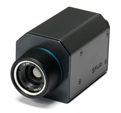
Teledyne FLIR A35 / A65 Features
Extremely Affordable and Compact
Teledyne FLIR’s Ax5 Series models are low-cost thermal imaging temperature sensors that are ideal tools for monitoring temperatures in automation or machine vision.
High Thermal Sensitivity and Image Quality
The Teledyne FLIR Ax5 Series produces high quality thermal images that can show temperature differences as small as 50 mK. Record crisp 640 x 512 pixel thermal images with the Teledyne FLIR A65, or for less precise applications, the A35 generates a 320 x 256 pixel thermal image that still allows you to easily track temperature changes.
GigE Vision™ Standard Compatibility
GigE Vision is a camera interface standard developed using the Gigabit Ethernet communication interface. GigE Vision is the first standard to allow for fast image transfer using low-cost standard cables, even over long distances.
GenICam™ Protocol Support
The goal of GenICam is to provide a generic programming interface for all types of cameras. This protocol also makes it possible to use third party software with the camera.
14-bit Temperature Linear Output
Allows for non-contact temperature measurement within any third party software. A built-in Gigabit Ethernet connection allows real time 14-bit image streaming to a computer.
Synchronization
Possible to configure one camera to be master and others to be slave(s) for applications that call for more than one camera to cover the object or for stereoscopic applications.
Teledyne FLIR A35 & A65 Technical Specifications
| System Overview | FLIR A65 | FLIR A35 |
| IR resolution | 640 × 512 pixels | 320 × 256 pixels |
| Spatial resolution (IFOV) | 90° × 69° with 7.5 mm lens | 63° × 50° with 7.5 mm lens |
| 45° × 37° with 13 mm lens | 48° × 39° with 9 mm lens | |
| 25° × 20° with 25 mm lens | 24° × 19.2° with 19 mm lens | |
| 12.4° × 9.92° with 50 mm lens | 13° × 10.8° with 35 mm lens | |
| 6.2° × 4.96° with 100 mm lens | 7.6° × 6.08° with 60 mm lens | |
| Image frequency | 30 Hz | 60 Hz |
| Detector data | ||
| Detector pitch | 17 µm | 25 µm |
| Measurement | ||
| Object temperature range | -25°C to 135°C (-13 to 275°F) / –40°C to 550°C (-40 to 1022°F) | |
General
| Imaging & Optical Data | |
| Thermal sensitivity/NETD | < 0.05°C @ 30°C (86°F) / 50 mK |
| Accuracy | Accuracy ±5°C (±9°F) or ±5% of reading |
| F-number | 1.25 |
| Focus | Fixed |
| Detector data | |
| Focal Plane Array (FPA) / Spectral range | Uncooled VOX microbolometer / 7.5–13 µm |
| Detector time constant | Typical 12 ms |
| Ethernet | |
| Ethernet | Control and image |
| Ethernet, type | Gigabit Ethernet |
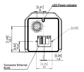
| Ethernet, standard | IEEE 802.3 / RJ-45 |
| Ethernet, communication | GigE Vision ver. 1.2 Client API GenICam compliant |
| Ethernet, image streaming | 8-bit monochrome @ 7.5 / 30 / 60 Hz (variant dependant) Signal linear/ DDE, Automatic/ Manual, Flip H&V 14-bit @ 7.5 / 30 / 60 Hz (variant dependent) according to IR camera resolution Signal linear/ DDE, GigE Vision and GenICam compatible |
| Ethernet, power | Power over Ethernet, PoE IEEE 802.3af class 0 Power |
| Ethernet, protocols | TCP, UDP, ICMP, IGMP, DHCP, GigEVision |
| Digital input/output | |
| Digital input | General purpose , 1× opto-isolated, “0” < 2, “1”=2–12 VDC |
| Digital output, purpose | General purpose output to ext. device (programmatically set) |
| Digital output | 1× opto-isolated, 2–40 VDC, max 185 mA |
| Digital I/O, isolation voltage | 500 VRMS |
| Digital I/O, supply voltage | 2–40 VDC, max 200 mA |
| Digital I/O, connector type | 12-pole M12 connector (shared with Digital Synchronization and External power) |
| Synchronization In, purpose | Frame sync in to control camera |
| Synchronization In | 1×, non-isolated |
| Synchronization In, type | LVC Buffer @3.3V, “0” <0.8 V, “1”>2.0 V. |
| Synchronization Out, purpose | Frame sync out to control another Ax5 camera |
| Synchronization Out | 1×, non-isolated |
| Synchronization Out, type | LVC Buffer @ 3.3V, ”0”=24 MA max, “1”= –24 mA max. |
| Digital Synchronization, connector type | 12-pole M12 connector (shared with Digital I/O and External power) |
| Power system | |
| External power operation | 12/24 VDC, < 3.5 W nominal < 6.0 W absolute max |
| External power, connector type | 12-pole M12 connector (shared with Digital I/O and Digital Synchronization ) |
| Voltage | Allowed range 10–30 VDC |
| Environmental data | |
| Operating temperature range | –15°C to 60°C (+5°F to 140°F) |
| Storage temperature range | –40°C to 70°C (–40°F to 158°F) |
| Humidity (operating and storage) | IEC 60068-2-30/24 h 95% relative humidity 25°C to 40°C (77°F to 104°F) |
| EMC | EN 61000-6-2 (Immunity) EN 61000-6-3 (Emission) FCC 47 CFR Part 15 Class B (Emission) |
| Encapsulation | IP 40 (IEC 60529) |
| Bump | 25 g (IEC 60068-2-27) |
| Vibration | 2 g (IEC 60068-2-6 & MIL-STD810G) |
| Physical data | |
| Weight | 0.21 kg (0.46 lb.) |
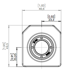
| Camera size (L × W × H) | 106 × 47 × 50 mm (4.2 × 1.9 × 2.0 in.) |
| Tripod mounting | UNC ¼”-20 (on three sides) |
| Base mounting | 4 × M3 thread mounting holes (bottom) |
| Housing material | Magnesium and aluminum |
| Scope of delivery | |
| Packaging, contents | Cardboard box, thermal imaging camera with lens, focus adjustment tool, printed documentation, user documentation CD-ROM, FLIR Tools download card |
The FLIR A35 & A65 may be ordered with one of five lens options each. Below are field of view calculators for each camera/lens option.


